Allen Bradley Inverter Hookup

All things related to Centroid Oak, Allin1DC, MPU11 and Legacy products

Moderator: cnckeith

Post Reply
9wdragline
Posts: 10
Joined: Mon Dec 31, 2018 4:06 pm
Acorn CNC Controller: No
Allin1DC CNC Controller: Yes
Oak CNC controller: No
CNC Control System Serial Number: 20422
DC3IOB: Yes
CNC12: Yes
CNC11: Yes
CPU10 or CPU7: No
Location: Pittsburgh,PA

Allen Bradley Inverter Hookup

Post by 9wdragline »

Need some help hooking up this inverter. I am using it manually right now but want to get it working with my control.
I was talking to a couple of the Centroid reps last weekend at the Cabin Fever Expo in Lebanon Pennsylvania to see if they could help me.
Very nice guys by the way.

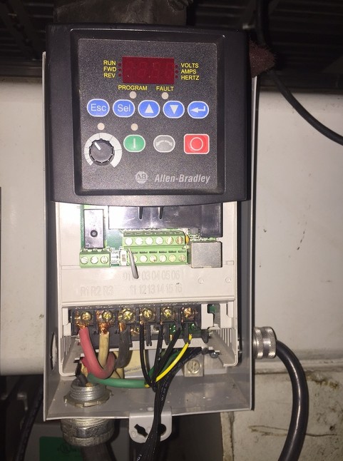
Allen Bradley 22B-B017N104
Image
Image

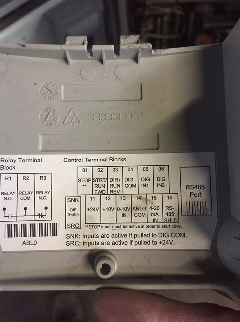
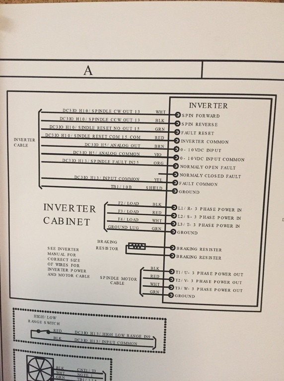
Here is the diagram for the inverter. I penciled in what I think is correct but uncertain where MA MC S4 go.
Image

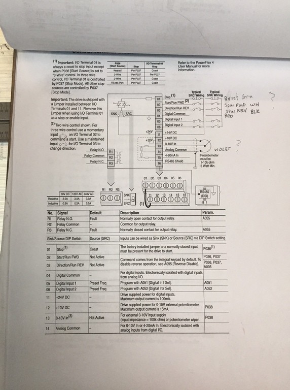
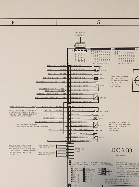
A couple shots from the wiring diagram from Centroid
Image
Image

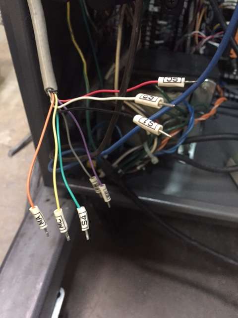
My control originally had an inverter hooked up but gone when I got it but the wires are there.
Image
9wdragline
Posts: 10
Joined: Mon Dec 31, 2018 4:06 pm
Acorn CNC Controller: No
Allin1DC CNC Controller: Yes
Oak CNC controller: No
CNC Control System Serial Number: 20422
DC3IOB: Yes
CNC12: Yes
CNC11: Yes
CPU10 or CPU7: No
Location: Pittsburgh,PA

Re: Allen Bradley Inverter Hookup

Post by 9wdragline »

Bump

Can any one help me with this hookup?
cncsnw
Posts: 3855
Joined: Wed Mar 24, 2010 5:48 pm

Re: Allen Bradley Inverter Hookup

Post by cncsnw »

Those look like typical wire labels and colors for a Yaskawa 606-series inverter (e.g. PC3 or V7).

SC RED = sequence common -> 04
S1 BLK = run forward (or maybe run reverse) -> 02 or 03
S2 WHT = run reverse (or maybe run forward) -> 03 or 02
S4 GRN = reset -> 05 or 06 (you may have to set a parameter to configure an input as reset)
MC YEL = fault relay common -> R2
MA ORG = fault relay output -> R3 or R1 (depends on your PLC program logic)
FR BRN = 0-10V analog reference -> 14
FC VIO = analog common -> 13

You will either need a jumper from 04 to 01 as described in the A-B manual, or you can branch off of OUT14 "Spindle Enable N.O." to terminal 01, so it is closed whenever the spindle needs to run in either direction.
Post Reply