Lube pump fault input questions

All things related to Centroid Oak, Allin1DC, MPU11 and Legacy products

Moderator: cnckeith

bloomingtonmike
Posts: 114
Joined: Wed Sep 11, 2013 1:31 am
Acorn CNC Controller: Yes
Allin1DC CNC Controller: Yes
Oak CNC controller: Yes
CNC Control System Serial Number: 0916130849
DC3IOB: No
CNC11: Yes
CPU10 or CPU7: No

Re: Lube pump fault input questions

Post by bloomingtonmike »

Maybe I am interpretting this wrong?

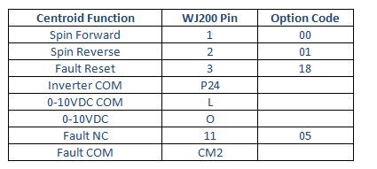
I was reading CM2 on wj200 to inp9-12 on allinonedc and Fault input on allinonedc to 11 on wj200.

Guess I am dense and want a line drawing like the other inverters had LOL.


Image
Mikie in Bloomington IL
AMDlloydsp
Posts: 91
Joined: Thu Oct 17, 2013 4:32 pm
Allin1DC CNC Controller: Yes
CNC Control System Serial Number: 0605130770
DC3IOB: No
CNC11: Yes
CPU10 or CPU7: No

Re: Lube pump fault input questions

Post by AMDlloydsp »

bloomingtonmike wrote:Can we discuss Lube pumps for a minute.

I am confused.

First off my pump only has four wires. Black, White, Green, Red in that order. It is a 110V pump.

I was thinking I would:
run hot/line through the output for Lube (3&4 terminals on top of controller)
Run 110 neutral to the pump
run 24V+ through the pump (in green out red) and into the lube fault input
24V common to the lube fault common bank (cant remember the numbers off hand - either 5-8 or 9-12)

I did that and nothing happened.

Then I ran 24V+ from the 24VDC ps straight into the lube input, completely bypassing the pumps red and green wire, and when I started up everything I got a lube error and the estop tripped.

Tried it again with no 110V or neutral going to the pump at all. Same thing - lube fault error and contactor coil opens.

That really confused me.

Does the lube fault input trip when it sees 24V? I was expecting, since I thought it was expecting the switch to be NC that it wanted 24V+ on that terminal??

I hooked up just 110V to the pump and no conttroller - pump sounds like it is running just fine.

Any advice?

I do not see a name brand on my pump. At this point I am guessing I need to do something else for that lube fault input though.

Mikie

Yeah... it sounds pretty much like a Bijur or a Bijur clone. The red and green wires are the float switch that sense the oil level in the tank. Closed is 'empty', so when you connect 24VDC directly to the Lube Fault input, you're simulating an 'empty' condition. The float switch is usually just a magnetic reed switch closed by a magnet in the float. If your pump happens to output an open switch when empty, you still connect everything the same as below, and change the STATE it senses in the software parameters. The hookup is the same, either way.

Almost as you did before, connect green to +24VDC(plus). Connect -24VDC(minus) to AIODC lube-fault 'common' pin (9-12 common) on H10 and the red lead from the pump to the Lube Fault input. "Nothing happened", because you didn't include "common" in the circuit. When the switch closes in the tank float, it lights up the LED side of an opto-isolator on the AIODC, but you supplied no 'return' circuit for the power. "Nothing will happen", too, if you have oil in your tank. It only signals a fault when the tank is empty. (again, if yours puts out an 'open' when empty, then just change the parameter for it, don't change the hookup).

The output relays on the AIODC are rated for 5A at 277VAC, but I add another heavier mechanical relay or SSR between the AIODC and any AC-powered accessory, just to be safe. (Old electronics guy from the '70s, and habits are hard to break)

White and black on your pump are (as you surmised) the pump motor power.

You really should look at the schematic in "LubePump.pdf" in the docs files.

Lloyd
bloomingtonmike
Posts: 114
Joined: Wed Sep 11, 2013 1:31 am
Acorn CNC Controller: Yes
Allin1DC CNC Controller: Yes
Oak CNC controller: Yes
CNC Control System Serial Number: 0916130849
DC3IOB: No
CNC11: Yes
CPU10 or CPU7: No

Re: Lube pump fault input questions

Post by bloomingtonmike »

Sorry for not being clear. I got the pump fixed up last night. Just a matter of setting 178 and turning it on with 179 in a time variable I could test it with. My float switch was NO.

Then tonight I read cncsnw's post about using the alarm so I enabled that and it works perfect. I used AL1 as it is NC by default vs AL2 that is NO by default (yes I know either can be set to NO or NC). I ran 0VDC to AL0, AL1 to inp10 Spindle fault, and 24VDC to 9-12common. I also changed estop and low lube to each have 0vdc at inp12 estop and inp9 low lube. Set 178 to 1 (since like stated above my float switch is NO). Perfect.


Now to learn about homing.

Also I have not seen a files section that had a pump pdf on it. Where is the link to that????
Mikie in Bloomington IL
AMDlloydsp
Posts: 91
Joined: Thu Oct 17, 2013 4:32 pm
Allin1DC CNC Controller: Yes
CNC Control System Serial Number: 0605130770
DC3IOB: No
CNC11: Yes
CPU10 or CPU7: No

Re: Lube pump fault input questions

Post by AMDlloydsp »

http://www.ajaxcnc.com/tech/downloads/s ... matics.rar

(You'll need WinRAR or another sort of windows archive expander to get the files out of the compressed archive)

Lloyd
bloomingtonmike
Posts: 114
Joined: Wed Sep 11, 2013 1:31 am
Acorn CNC Controller: Yes
Allin1DC CNC Controller: Yes
Oak CNC controller: Yes
CNC Control System Serial Number: 0916130849
DC3IOB: No
CNC11: Yes
CPU10 or CPU7: No

Re: Lube pump fault input questions

Post by bloomingtonmike »

Thank you guys all for all the help and links. Great group.
Mikie in Bloomington IL
polaraligned
Posts: 231
Joined: Mon Feb 07, 2011 8:03 pm
Acorn CNC Controller: No
Allin1DC CNC Controller: No
Oak CNC controller: No
CNC Control System Serial Number: 1030090103
DC3IOB: Yes
CNC12: Yes
CNC11: Yes
CPU10 or CPU7: No
Location: Montvale, NJ

Re: Lube pump fault input questions

Post by polaraligned »

Yeah, there are about 10 different ways to wire that inverter....
AMDlloydsp
Posts: 91
Joined: Thu Oct 17, 2013 4:32 pm
Allin1DC CNC Controller: Yes
CNC Control System Serial Number: 0605130770
DC3IOB: No
CNC11: Yes
CPU10 or CPU7: No

Re: Lube pump fault input questions

Post by AMDlloydsp »

That said, I don't understand why you are trying to use CM2 and the open-collector outputs at all.

Doesn't your inverter report a fault using its alarm relay output (terminals AL0, AL1 and AL2)?

If so, you should connect +24VDC to the INP9-12 common terminal on the PLC; connect 0VDC to the AL0 terminal on the inverter; and connect AL2 to INP10. Then change Parameter 178 from 3 to 1, since you will have a normally-closed inverter fault signal.[/quote]
-----------------------------------------------
You're correct that his inverter SHOULD output the alarm as a relay closure. But let's say (just for grins) that it didn't.

Then a pullup resistor to +24 with the other end of the resistor going to the inverter fault input, and with -24 going to common AND the inverter "fault" common, THEN an OC output on the inverter would apply the signal he wants. It's probably not necessary (as you said, and maybe not even possible on his inverter), but it would work.

There are fifty ways to skin this cat.

Lloyd
Post Reply